Saturday, 22 September 2012

Propeller-Powered Car


Purpose:
The purpose of this project was to give a gental introduction to mechatronics. Mechatronics is the combination of mechanical and electrical engineering. For an introduction to mechatronics there couldn't be a better thing to make than a car. Because we didn't know much about mechatronics the car design was simplified by using a fan to power the car rather than a gear box.

Procedure:
We were first told the parts that we would be supplied with. It was up to us to decide what to use for the chasis, wheels, axis and how we were going to adhere both the parts and the circuit. The thing that effect my car the most was my chasis decision. My original Idea was to cut a piece of acrylic but after comparing it to my other chasis idea (a small project box) I decided that the piece of acrylic was too heavy. The thing that I did not consider however was the center of gravity of my car. Even though I made my car lighter by choosing a small project box I focused almost all of the car's weight on one point therefore the car required more power to move such a condensed weight. Because of this the other cars that weighed more than mine went faster than mine because they had better weight distribution.

Circuit Description:
The two main components of my circuit were the LDR and the TIP122. The Light Dependant Resistor either creates more resistance if there is low light for less resistance if there is a lot of light. The TIP122 is two transistors in a darlington pair. The typical role of a transistor is to amplify the current running through it. In this case we need a lot of current to power the fan so we used the TIP122. The TIP122 is special because it has two transistors in a Darlington pair. This means that instead of the current getting amplified once it is now getting amplified twice. Therefore the total current gain is the two individual gains multiplied together. For more information click here.

Realizations and Goals:
After racing my car it was obvious what I had done wrong. I had put all of my car's weight on one area. Because of my car's mass distribution it was unable to accelerate as intended and never maintained speed. Acceleration is affected by the mass distribution. The more condensed the mass the more force required to move the object. If I had have used the acrylic for the chasis of my car I think that it would have been faster. The one correct choice I made however was in regards to my wheels. Without thinking much of it I chose the smallest wheels. At the time I chose them because they suited my car the best but they actually had a positive affect on my car. Because the wheels were so small they had a smaller moment of inertia. Moment of inertia describes how difficult it is to change the angular motion of the axis. It is not just based on how much mass the object has overall, but how far each bit of mass is from the axis. The further out the object's mass is, the more rotational inertia the object has, and the more rotational force (torque, the force multiplied by its distance from the axis of rotation) is required to change its rotation rate. Because I used those small wheels it allowed the fan to move my car. If I had have used bigger wheels I am doubtful my car would have moved at all. For the next project I will be more aware of my weight distribution but use the same wheels I used for this project. 

Parts List:
Parts given:

Quantity
Part
Description
1
DC Motor
4.5V, 32000 rpm
1
Propeller
4-blade plastic
4
AA Battery

1
Battery Holder

1
LDR

1
Resistor
1M Ω, 1/4W
1
TIP122
NPN Darlington Pair


Chosen parts: 

Quantity
Part
Link
1
Project Box
4
Metal axel
4
Wheels


Wednesday, 9 May 2012

Tune Player

Click the icons below:


Purpose:

The purpose of this project was to try our hand at producing audio through Arduino. After spending the majority of the year on temperature we decided that looking into sound would be a great way to finish the year on a high. As we got deeper into the project it became less about trying to produce sound as to trying to improve the somewhat weak code that we were provided. The project then became a problem solving assignment as well as a test of our creativity based on what we wanted/were determined to add. 


Procedure:

We first looked at the circuit design that was in 30 Projects for the evil Genius and after getting a general understanding we built it. Then we looked at the Tune Player code from 30 Projects for the Evil Genius to get a sense of how the sounds were created and the method in which the author used to play songs. After we had a better understanding of the code that was provided we uploaded the sketch and ran it. We noticed right away that the tune player was not what we expected to hear. We thought about ways to improve it such as adding sharps, multiple octaves, and different note durations. After completing all the improvements we ran the new sketch and the difference was amazing. 


*IMPORTANT*
The array sin16[.......] in my Arduino sketch is VERY important. It simulates a sin wave. Because we are using a 4 bit amplifier we can only get a maximum of 16 points on our sin wave. 7 being the middle, 15 being the maximum and 0 being the lowest (0-->15 = 16....dont be off by one). The matrix toneDurations[3]12]{...} determines the rate at which we run through the sin wave, hence the name toneDurations. It does not produce the sin wave but instead determine the frequency of the wave, therefore producing the pitch.

Parts List:
1 100nF non-polarized capacitor
1 100uF, 16v electrolytic capacitor
5 10k ohm resistors
3 4.7k ohm resistors
1 1M ohm resistor
1 100k ohm resistor
1 TDA7052 1W audio amplifier
Miniature 8 ohm loudspeaker

Check out R2R Digital to Analog converter overview 


Wednesday, 7 March 2012

ATtiny85 Port

Click the icons below:


Purpose:
The purpose of this project was to start us using the ATtiny85 so that we are familier with it when we use it in the greenhouse. Also the project introduced us to using the Arduino as a programmer, which will allow us to program many other chips for many other projects.

Procedure:
We first learned how to use the Arduino as a programmer. After uploading the ArduinoISP sketch and connecting the appropriate wires we then burned our LM35DZ sketch onto our ATtiny85. After troubleshooting for a while we found that adding an if statement was the best option instead of setting values.

Parts List:
ATtiny85
Any Transistor
MOSFET
LM35DZ
Fan
12v Power Supply

Circuit Picture:

Wednesday, 29 February 2012

ControlP5 library vs Serial library

Click the icon below:


Purpose of the serial library:
The purpose of the serial library is to connect Processing to an external microcontroller. In my Processing sketch we used the serial library to read the data off of an LM35DZ temperature sensor. Without the serial library Processing would be unable to read the data from the Arduino.

Purpose of the controlP5 library:
The purpose of the controlP5 library is to allow the user to interact with the Processing serial/output screen. The user can use dials, switches, buttons and sliders to manipulate the output on Processing's serial.

Click here for a tutorial on how to add a library to Processing

Links:

   Serial                    ControlP5


Sunday, 26 February 2012

Full Fan Control


Click the icons below:


Purpose:
The purpose of this project was to introduce us to interrupts in the Arduino environment. Using interrupts in the future will provide us with more accurate code and will allow us to create and run more complex sketchs.

Procedure:
We used the code from last week but implemented everything needed for interrupts and the rpm equation. The rpm equation is (rpm = 30000/(millis() - timeold)*rpmcount;30000 is the base line for the rpm. There are 60 seconds in a minute and 1000 milliseconds in a second. We then devide 60000 by two because the fan sends a signal every half rotation. (millis() - timeold) is the amount of time it took to do one full rotation. In other words it is simply (total time - the last time recorded). rpmcount un we multiply it by rpmcount because in the sketch we only display it when rpmcount is 100. If we didn't  multiply it by rpmcount o we would be returning one hundred rotations per minute.
Output
Parts list:

Full parts list

Basic parts list:

RFP30N06 MOSFET
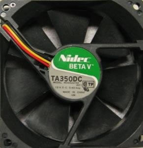
TA350DC Fan
LM35DZ
Diode


Friday, 10 February 2012

Air Flow Management

Click the icons below:


Purpose:
The purpose of this project was to allow us to run a higher load and the Arduino with the use of only one power supply. In this case we are running a 12v fan. We are continuing with the intention of incorporating our projects in a green house. A proper greenhouse should have its air in constant motion and this project allows us to do just that. The fan changes speeds depending on the temperature to allow for different air flow and to reduce the overall temperature of the green house. 

Procedure:
We started with creating a homemade DC jack the takes the Vin on our board and feeds the power to the Arduino. Next we set up a breadboard that lets us control the fan with the Arduino. We can run this higher load by using a MOSFET. After, we used an LM35DZ to minitor the temperature and used the map function to control the speed of the fan based on the temperature. We calculated the time by using the millis() function in Arduino and dividing it by 1000 to display it in seconds. We calculated the volts being used by using the map function again. To format the serial monitor we used a series of print("\t") and println()'s.

Parts list:

Full Parts List:
LM35DZ
Diode


Pictures:

Monday, 30 January 2012

5V/12V Breadboard-Compatible Regulator


Click the icons below:


Purpose:
The purpose of this project was to introduce us to making our own boards and to start us using Eagle. Eagle is a professional breadboard making program. It allows you to make a schematic and breadboard demo of your circuit as well as allow you to print your board view out.

Procedure:
We first made a simple circuit with one resistor and an LED to get ourselves accustomed to board making. Then we watched Jason's tutorials on Eagle and learned how to use it as a class. We made his demo project and used his tips and tricks to design our own board. We made our schematic in Eagle, changed it to board view and then we printed it straight from board view. We then took a regular household iron and ironed on the printed version of our breadboard onto a piece of single sided copper board. After the design was on we made sure that everything was connected. If there was a piece we were not sure about we just took a sharpie and drew a line connecting them. Finally we took the board and let it soak in ferrous chloride acid for thirty minutes. When the process was complete we drilled the holes we needed and soldered the pieces to the board.

Parts List:
Full Parts List

Pictures:
Eagle Board
Eagle Schematic
5v DMM Reading
RAW DMM Reading
Pre-soldered board beside negative